Here’s the link to the files (the link and login are all case sensitive):
http://files.advsolinc.com:100/ASIFileServer
please send an email to dbutts@advsolinc.com to get the user name and password - you must have been an attendee to receive the files
files for both Revit MEP and ACAD Architecture are available to download from this site. Check back regularly between now and Jan. 31st, as I will be making updates to the template.
Thanks for the patience and for coming to the classes!
David B.
Monday, December 15, 2008
Thursday, December 11, 2008
AU Class Content Update
I'm currently working with our IT department to set up a secure site for the content for AU - the plan is to have this link go live sometime Friday afternoon/Saturday morning with a sample Revit MEP template, shared parameter file and ACAD MEP template. Watch this blog for updates, I'll send the login name and password out to all that have emailed as soon as it goes live.
Also, the handouts are available under the new AU website - go to the list of classes for 2008, pick the course, and choose materials. YOu should be able to download the files, as long as you were an attendee.
Thanks for all the interest!
David B.
Also, the handouts are available under the new AU website - go to the list of classes for 2008, pick the course, and choose materials. YOu should be able to download the files, as long as you were an attendee.
Thanks for all the interest!
David B.
Monday, December 8, 2008
AU's in the Can!!!
Man, what a week...but it's finally done.


First off, THANKS to all the great class attendees - it's always very humbling and exciting to have great crowds in the classes. Everyone played along and put up with all the corny jokes and country music....as well as the confetti and marshmellows (apologies to the cleaning crew). I'm always honored to have the opportunity to do this - and hopefully help you be as excited about the technology and motivated about your future. The tools continue to get better and better, so there's much to look forward too.
What makes the AU classes different from traditional training classes and venues? I think my motivation comes from a variety of different sources - but the key source was to sit through classes that I didn't enjoy or that bored me to tears. I was never a great student - maybe because I despised book reader style instructors. The ones I remember the most (such as Frank Pattenelli, my physics prof in college that was a retired engineer that didn't have to work, but taught because he enjoyed it) are the ones that related what I was learning to real life. They spent as much time focusing on why this was important to me and my career - rather than simply approaching the material as "you have to have my course to graduate".
But AU is not a typical class - you're trying to reach 100-200 people at once and hopefully coming up with a common thread that interests all - and that's where the humor comes in. My mother has been a family nurse practictioner and motivational speaker to healthcare groups for many years, and was published in a couple of books about humor in the medical profession (talk about a tough topic). She'll dress up like Minnie Pearl (if you don't know who this is, you may be too young to read this, so try google) and start every session off with a big "HOW-DEE"! Over the years, I've had many people come up to me and tell me that's what they remember - her humor and her honest passion for the profession.
You can't deliver an memorable session unless you really believe in what you're doing, so the key is to stand out from the crowd - if you're not passionate about what you're teaching, it's impossible for that to carry through to your audience. I've always throughly enjoyed my work, and that helps. Having the backing of my company to participate has been essential, but wanting to be there and share the passion is what makes it successful.
Make the topic is something you know well enough that you can present without reading from the script - your own confidence in the topic will carry through to others. If they can watch you do the work without having to check yourself or flip through a handout, they'll believe they can do this, too.
And the most important part is to simply HAVE FUN - you only have 90 minutes in most cases, so find a topic that's important to you, and tell people why - and be able to laugh at any situation. The ones that take themselves too seriously are the ones that miss the point, so don't be afraid to put the clown glasses on and have a little fun (especially when it's at someone else's or your own expense).
Once again, thanks for making the event as much fun for me as I hope it was for you - and I hope the technical content was helpful as well. As soon as the new AU site is up, I'll get some extras posted for you to my course pages...so stay tuned, and we'll see you next year!
thanks - David B.
Wednesday, November 26, 2008
New Content for Revit MEP 2009 - Fittings
If you are a subscription member for Revit MEP, there is a new content extension you can download that includes new fittings for piping and duct. One important note and comment is that it does not follow the existing folder locations - for example, new pipe content was placed in a material folder a la ACAD MEP - in other words, look in the Gray Iron and Malleable Iron folders for the new fittings - but duct wasn't done the same way. Look for the new fittings in the existing duct folders. I'm assuming this will be reorganized again in the next release, so if it's doen around materials that would be fine. Move as you see fit - and make sure you put the lookup tables in the correct locations.
Here are the notes from the ReadME file:
Installation Instructions
The content contained in the RME 2009 Content Extension will not overwrite any of the default content that was originally installed by Revit MEP 2009. All of the Extension content is new and have names different from any of the original content names. When you install the Extension to the same location as your existing content, many of the new content families will install in folders that already exist. A notable exception is that all of the new pipe fittings have been re-organized to be grouped by material type rather than by category. The end result is that your original pipe fittings will remain as is (organized by category folders) and the new pipe fitting folders will be adjacent to those folders and organized by material type.
IMPORTANT:
The fittings that are included in the RME 2009 Content Extension will not function properly if their associated lookup tables are not installed in the correct location. These lookup tables (.csv files) need to be installed in the same location as your current lookup tables.
The default installed location for the "LookupTables" folder is:
Windows XP: C:\Documents and Settings\All Users\Application Data\Autodesk\RME 2009
Windows Vista: C:\Program Data\Autodesk\RME 2009
If you are unsure where your "LookupTables" folder is located, you can find this information in the "Revit.ini" file. This file is located in the same folder where Revit MEP 2009 is installed. In this file, search for "LookupTableLocation". This will indicate where your lookup tables are installed.
For example:
LookupTableLocation=C:\Documents and Settings\All Users\Application Data\Autodesk\RME 2009\LookupTables
When you run the self-extracting ".exe" file to install the RME 2009 Content Extension, you will be prompted to choose a location to extract the content files. You should browse to the path indicated in your "Revit.ini" file, and stop one level above the "LookupTables" folder. In the example listed above, you should browse to and select the following folder:
C:\Documents and Settings\All Users\Application Data\Autodesk\RME 2009
This will ensure that the new lookup tables contained in the RME 2009 Content Extension will be installed to the correct location.
Alternatively, you could extract the new content to any location that you desire, and then manually move the contents of the newly extracted "LookupTables" folder to the correct "LookupTableLocation" location, as specified in the "Revit.ini" file.
Wednesday, November 19, 2008
AutoCAD MEP Electrical Devices - A quick spin..
Rather than create device styles from scratch, it's easier to use what's already in the program to make what you need. This is actually one of the simplest items to edit when it comes to object based content in AutoCAD MEP 2009 - if you can edit a block and revised which blocks are used in a device style, you can create this content.
Here are some high level step-by-step procedures you can use:
1. Make a copy of the master drawing located in the AECB Content folder.
2. Open the master drawing for the type of device.
3. Use the block editor to locate and edit similar block symbols of the desired part. Once the block is open, use the Save As icon to create a copy, then edit the copy. When naming the block, use lower case letters so it can easily be differentiated between OOTB content and custom content.
4. From the electrical menu, go to device > Styles.
5. To edit an existing style, go to the views tab first, and note the name of the plan view block – that should be the block that was edited. If the block was duplicated to make a new version, change the view block to the new block.
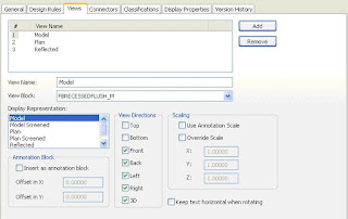
6. Change the view block for both the plan and reflected view names.
7. If the item is to adjust its size with the drawing scale (such as a receptacle or switch), make sure the Use Annotation scaling option is checked.
8. If the device style does not exist, take a device that is similar to the desired device – right click on the style in the style manager, and then choose Copy. Right click again and choose paste to create a new style. Edit the copied style and change the name to the new style.
9. SAVE the drawing after each main step or new style. Audit frequently.
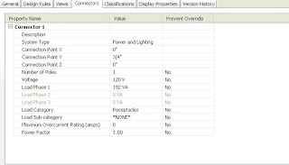
10. Once the style is created, edit the connector styles for the following items:
- Number of poles
- Voltage
- Load Phase 1 if single pole, edit all if 3 pole
- Load Category
- Description
- Y Connection point.
11. After the connectors are edited, go to the general tab.
12. Select Property Sets. If the desired style-based property sets are not in the drawing, load them from the master schedules and tags drawing under the styles folder (which is lcoated in the ALL USERS documents and settings folder.
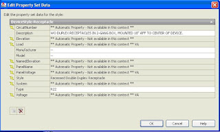
13. Anything that applies to all examples is style based, and should be part of the property sets in this master drawing. Edit as specified by the client to include default values, so schedules can be populated as needed.
14. If changes are made to the property set definitions, make sure they are copied back to the master template so they match. This way, the default values won't be overwritten when importing the symbol.
Hope this helps - thanks - David B.
Here are some high level step-by-step procedures you can use:
1. Make a copy of the master drawing located in the AECB Content folder.
2. Open the master drawing for the type of device.
3. Use the block editor to locate and edit similar block symbols of the desired part. Once the block is open, use the Save As icon to create a copy, then edit the copy. When naming the block, use lower case letters so it can easily be differentiated between OOTB content and custom content.
4. From the electrical menu, go to device > Styles.
5. To edit an existing style, go to the views tab first, and note the name of the plan view block – that should be the block that was edited. If the block was duplicated to make a new version, change the view block to the new block.

6. Change the view block for both the plan and reflected view names.
7. If the item is to adjust its size with the drawing scale (such as a receptacle or switch), make sure the Use Annotation scaling option is checked.
8. If the device style does not exist, take a device that is similar to the desired device – right click on the style in the style manager, and then choose Copy. Right click again and choose paste to create a new style. Edit the copied style and change the name to the new style.
9. SAVE the drawing after each main step or new style. Audit frequently.
10. Once the style is created, edit the connector styles for the following items:
- Number of poles
- Voltage
- Load Phase 1 if single pole, edit all if 3 pole
- Load Category
- Description
- Y Connection point.

11. After the connectors are edited, go to the general tab.
12. Select Property Sets. If the desired style-based property sets are not in the drawing, load them from the master schedules and tags drawing under the styles folder (which is lcoated in the ALL USERS documents and settings folder.

13. Anything that applies to all examples is style based, and should be part of the property sets in this master drawing. Edit as specified by the client to include default values, so schedules can be populated as needed.
14. If changes are made to the property set definitions, make sure they are copied back to the master template so they match. This way, the default values won't be overwritten when importing the symbol.
Hope this helps - thanks - David B.
Finally...IES Virtual Environment - We're Resellers!

After a year of working out the details, and getting all the i's dotted and t's crossed, Advanced Solutions is now a reseller of the IES Virtual Environment products. These tools, when used in conjunction with Revit Architecture and MEP, expand the level of analysis that can be used in conjunction with the Revit model. I've had the fortune to provide overview of this product both last year and this upcoming year at Autodesk University, and I can't tell you how happy I am that we're finally able to do this.
For details on the products, visit this website: http://www.iesve.com/ - this will show the main product lines, including VE-Ware, the VE Toolkits and the new Architectural Suites.
As Autodesk also continues to develop and introduce their own analysis software packages, we're on course to be in a position to help the end user choose which applications work best for them and fit their needs. Working in conjuction with our upcoming new releases of Revit MEP custom courseware (include items such as the Revit MEP Family Creation manual, and more), we want to make sure that we're covering as many bases as possible when it comes to the MEP design engineering market.
For more information about Advanced Solutions, check out the website at http://www.advsolinc.com/.
See you at AU!!!
Thanks - David B.
Monday, November 17, 2008
Working with Analysis applications
A few notes here...
If you haven't already downloaded the IES VE-Ware, try this link:
http://www.iesve.com/content/default.asp?page=s133
This includes come carbon footprint tools as well as the Architecture 2030 challenge - we'll be talking about it in both Revit MEP analysis labs this year (they're both the same session, just a repeat due to the volume of registrations.
Also - I had a few Trace users point a couple of items out worthy of mention - while a good majority of the spaceengineeringobjects property set definitions in AutoCAD MEP export out to Trace 700 just fine, the Revit MEP export only takes physical geometry - and doesn't carry items such as u-values in openings or walls. Best bet is to just take the geometry, then setup templates in Trace to add items such as occupancy loads, power loads, etc. I haven't tried to roundtrip it back into Revit from Trace since I only have the trial version, but I'm sure someone could pipe up and say what actually will come back into Revit from Trace other than just the calculated loads.
One other item I discovered - HAP can read the xml file and get physical geometry as well, but won't export back to the Revit model...
So - what are you finding out when working with the analysis tools? Post your response here, let's see how others are doing...
thanks - dab
Creating spaces for mutliple project files...
I wanted to get this into the tips and tricks class at AU but ran out of time...I had a client that was using Revit MEP 2009 and creating multiple projects for each discipline, due to the size of the project they were working on. After goofing around with one of the projects, we found out that you can copy and paste spaces from one room to another - as long as the linked file is set to be room bounding, and as long as you stay on the same level. If the linked file has spaces, it will pick up the room geometry once you select finish from the options bar.
So, we tried it between two different projects using the same linked background - and it worked! Again, it only works level to level, and we couldn't get multi-level spaces to work, but if you didn't create your spaces before breaking a project up into smaller projects, this is a fairly quick way to set one up and then use it other files.
Try it out and let me know what you think -
thanks - David B.
Back in the saddle again
First things first...with AU two weeks away, it's starting to get busy. I've been added to an event called AU Unplugged, with a session titled Revit MEP - How's it going! The idea here is to give users a chance to show up and throw out a few ideas on how they're doing with the application, and as a group see if myself or others in the crowd can offer tips and suggestions, as well as discuss where we think the application should be going and doing. I've invited a couple of Autodesk folks to attend but haven't gotten any RSVP's yet, but hopefully they'll attend.
The session will be at 2:00pm in the Casanova ballrooms at the Venetian. Here's the link to the session: http://au.autodesk.com/sessions/detail/4321/
It's limited to 30 people - if you want to come raise a little cain, get there early, it's first-come first-served, with no reservations....
Next....tip of the day....
Tuesday, September 9, 2008
Welcome to Ecotect!
Autodesk has completed the acquisition of Ecotect, an MEP analysis application - here's a segment of the update from Autodesk:
"Autodesk® Ecotect™ software can measure how fundamental criteria – such as solar, thermal, shading, lighting, and airflow – will affect building performance in the conceptual and detailed phases of design. This capability to forecast building performance over time better equips architects and engineers to deliver more energy-efficient and sustainable building designs.
Autodesk Ecotect Version 5.60 is now available for purchase online. The software includes Ecotect, Weather and Solar Tool installs along with help files and tutorials, example weather data, and other useful resources for getting started.
Existing Ecotect license customers may upgrade their license to version 5.6 for a limited time at no additional cost. A limited 30-day free trial version is also available for download. The trial version provides all the functionality of Ecotect, Solar, and Weather tools, minus the ability to save or print."
You can get your trial copy at www.ecotect.com - try it out and let me know what you think.
thanks - David B.
Some Good Links for MEP Products...
Autodesk has a couple of resource sites dedicated to the MEP product line you might want to check out. Both are edited and created by Armundo Darling at Autodesk, an old friend of mine that's been on the bus for a long time and has always been extremely helpful to me. Here's the link to the Revit MEP Resource Center:
http://resources.autodesk.com/adsk/servlet/Revit-MEP/tutorials.htm
And here's the one to the AutoCAD MEP Site:
http://resources.autodesk.com/adsk/servlet/AutoCAD-MEP/tutorials.htm
Check them out when you get a chance -
Kyle Barnhardt also has a great blog with AVI's for Revit MEP - he's the product manager for Revit MEP:
http://inside-the-system.typepad.com/
And another buddy of mine (and fellow MEP ICE specialist) from Mastergraphics, Scott Brisk, also maintains a loaded MEP site for the AutoCAD side:
http://autocadmep.blogspot.com/
And here's his site for Revit MEP:
http://revitmep.blogspot.com/
Give these sites a visit - these guys are definitely the best in the business and provide valuable information about our products.
Happy Cadding - David B.
Practice Revit MEP Families
To do a little self training, I started experimenting with some family editing for annotation families. Revit MEP uses annotation families for device symbols that have to adjust for scale, so I've edited a couple with some suggestions from my buddy Rob, who is working his way through the program as well.
The idea was add some receptacles that including shading to indicate different usage. Since model families don't allow the use of fill regions as part of the family, we had started to just draw dense linework. After doing a little experimentation, I've started to make several of my own examples of shaded receptacles. We also have a receptacle label family that we made that allows the user to omit the label from the family itself. It uses a type mark label to go with the several subtypes of receptacles I made from the default duplex receptacle.
If you're interested in receiving these samples, send me an email and let me know what you think. The receptacle label is actually part of our custom training manual we (Advanced Solutions) has written specific to creating and editing families in Revit MEP.
Send your requests to my email address at dbutts@advsolinc.com.
thanks - David B.
Monday, September 8, 2008
David's Church of the Painfully Obvious - Part One, All in the Family
Welcome to church of the Painfully Obvious. In here, we'll try to find salvation as we muddle our way through the fun and games of Revit MEP.
As I go forth on this journey of personal discovery (or lunacy, depending on well you know me), my goal is to provide you with a few simple tips that I discover along the way. As you find your own moments of self awareness, please feel free to share this with us as we attempt to make it to the mountain top.
So here's today's sermon - it's titled, "All in the Family..." Enjoy..
1. Working with a client's symbols, my first discovery is that hosted elements don't have their generic linework for 2D symbols drawn on the plan view reference plane, but instead on the front or back elevation view. So, as I try to edit the linework for the lights, I found myself a little disoriented. To make life easy, I went and selected everything in the elevation view, then used a filter to deselect everything but the lines (at which point I used my cheap sunglasses (which is what I affectionately call the isolate element tool) to isolate the linework, making it a little easier to work with.
2. This led me to remember truth number 2 - use an existing family first that came with the program to make new ones - open an existing one and use Save As, and save them into a separate set of folders for your custom content. Thankfully, there's a lot more content in Revit MEP than there was in the past - so I used a wall-mounted light to make my wall mounted emergency lights, and simply made a few changes to the symbol lines and the model lines to show what I wanted.
3. One truth leads to the next - here I discovered that you can't use a fill pattern in a model family....bummer, it would have been nice to use a simple hatch pattern (oops, there's my AutoCAD reaching out), so it was back to the drafting board - I just added lines to fill in a gap. UPDATE: I did just learn that you can add fill regions to an annotation family - which works great since a lot of the electrical devices are created this way, so they can adjust for scale as text does in the model. Funny thing is, it's not clearly explained this way in the online help...but I guess that's why we're here....
4. The truths just keep on coming - I was able to take a bunch of symbols a buddy sent me, and drag them from Windows Explorer into my template - they were created in the previous release, so it had to convert them, but man it was easy - the only thing I had to watch out for was the light sources....
5. Another truthism - when you're working with Revit MEP, don't waste your time making ceiling-based, floor-based or wall-based content - they can't read through the linked backgrounds, which is what most of our users are doing. Instead, I used the mechanical equipment.rft file for (or electrical or whatever) - as long as it doesn't include ceiling, wall or floor in the name I'm good, but I definitely start from one of these to save time.
That's it for today's truths. Tomorrow, we'll work on figuring out how the Tampa Bay Rays are still on top of the American League East....
later - David B.
Friday, September 5, 2008
AU 2008 is coming!!!
I'm looking forward to this year's Autodesk University - the last year of a 3-year stint at the Venetian. I wanted to let everyone know how impressed I've been with the crowds and the facility. It's definitely a beautiful place to be, but with the crowds getting so much bigger, it's becoming a capacity issue. The guys that run AU - Joseph, June, etc. do a fantastic job of organizing this event and pulling it off every, year, so when you see them, say thanks.
And as far as the instructors, this is a great opportunity to learn from the best in the business. Every year I pick up something new from these folks, as they all bring unique perspectives and useful information that makes my life much easier.
As far as classes, I've got 4 that I'm happy to be teaching this year:
Revit MEP 2009 - Maximize your Building Performance Analysis - a 1.5 hour lab, where we look at how spaces and zones work, as well as integration with outside applications such as Trace, IES VE, Green Building Studio and more. This year - no flashlights, or Funkadelic - but it will have something....there are two sessions on this lab for this year, on Wednesday at 1:00pm and 5:00pm - as of today, there's still a little space in the 5:00 lab - don't worry, we'll be rocking and rolling, so don't show up tired!
If you're interested in being a lab assistant for this class, send me an email to dbutts@advsolinc.com - I'll need one more for each session, and it pays, too.
On Thursday this year:
Revit MEP 2009 - Tips and Tricks - a new 1.5 hour lecture on some of the best practices we've been developing over the past few years. I always wanted to do a class like this, and did a similar class on templates last year, but this goes far more in depth that we did in those classes. Best of all, you get a copy of my template - of which you can butcher up and edit to your little heart's content...and may be a few other surprises....
AutoCAD Architecture - Maximizing Your Wall Styles for Elevation Views - back for 2008! MY baby - my first love - well, everybody has one of those. Even though I'm a gung ho Revit MEP and AutoCAD MEP user, you always have a special place in your heart for the first. The product has definitely matured, and there's all kinds of things you can do to a wall in AutoCAD Architecture. So Santa's back with a brand new bag...and new props...so if you're using AutoCAD Architecture and want to get more out of it, this is a fun class to come to.
Sign up early and vote often - and I'll see you in Vegas!!!!
http:\\au.autodesk.com\
December 2-5, 2008
thanks - David B.
BIM for Autodesk - The Promise, Present - The AutoCAD BIM
The BIM side of AutoCAD is alive and kicking, thanks to a head start that allowed Autodesk to learn from some early mistakes. AutoCAD Architecture and MEP 2009 have both been around for a while, so the tools are pretty mature. In this environment (which is a BIM environment due to the fact that data is included with the object model that includes 3D components- building information modeling) There are a few areas I've found that are better but still need improvement:
- Electrical Panel schedules and circuiting are greatly improved, with side by side schedules now, and a more user-friendly Circuit Manager. Electrical load data is now stored in an external project database, instead of residing within a drawing file.
- Interference checking now includes both hard and soft interferences, which aid with clearances around objects such as panels, etc.
- The solution tips by themselves are a huge improvement - instead of just getting the "red circle of death" with no explanation of why things aren't working, you now get the "yellow triangle of hope" (I didn't make this up, this is what the folks at Autodesk told us -honest) - which provides solution tips for resolving the problem.
- Annotation scale tied to display configurations are a help, but if the user is following the intended process, this only helps when the user makes a mistake and has to change scale to fit a different size view, to have it fit on a sheet of paper. It's still a throwback to the world of having every view drawing in model space all stacked up on top of each other, and used in conjunction with a lot of layout tabs in one drawing. Nice and easy, but not as efficient as the view system of Project Navigator.
The overall design workflow is still around - place the equipment, add the connecting geometry and annotate the objects all still work the same way. But users are skipping over important parts of the application and missing the point.
Electrical is a great example - I've heard Building Systems users say they can't use the electrical components in ACAD MEP because the panel schedule doesn't look like what I've used. That's a load (no pun intended) - the symbols in the program show the same symbol that has been used for designing buildings for years. Where the process needs to change is that instead of storing my circuit/load data in some outside database such as excel, it should be embedded in the properties of the object and the style. Even if you're not using the panel schedule, you can still track loads when connecting the devices together in a circuit - and the program will tell you when you overload the circuit. The tag used to label the homerun will get its information from the device - so if you move items to another circuit, the tag will update.
It's this kind of process change the designers need to get used to. Instead of separating all of this data into different locations, the storage location becomes the object itself - utilizing the property set definitions. And the owners of the buildings are starting to realize that BIM products allow them to get this information in their CAD file - and are starting to require it as part of the deliverable.
Step 1 - Adding the Equipment
So how does it work? The designer started by selecting and placing primary pieces of equipment, such as air handlers, VAV boxes, power panels, lights, receptacles, pumps, etc. in the first segment. This is where AutoCAD deviates from Revit - Revit includes the step of assigning the components to systems, which creates a "target-source" relationship (i.e., the VAV box is a source to an air terminal, which is the target). AutoCAD doesn't track that relationship, although items such as air flow to an air terminal are assigned when placed.
The analysis tools used to determine the equipment sizes are also different at this point between AutoCAD MEP and Revit MEP. With both applications, spaces and zones are utilized to determine items such as volume, square footage, etc. Other items such adjacencies to other spaces has to be manually inserted, but both applications will recognize items such as openings for windows and doors. Revit will recognize more properties of these openings automatically, whereas in AutoCAD, you have to utilize the Space/Zone manager to identify the type of opening, location within the building, etc. We'll talk more about this in Revit section...
Both applications export to gbXML files, which are used by applications such as Trane Trace 700, Green Building Studio, and others to provide a more detailed analysis of items such as heating and cooling loads. Revit includes a portion of the IES Virtual Environment that quickly performs an Apache-based heating and cooling load analysis based on a calender year, with location, service type, building type and other design criteria that's embedded in the model. Some of this data can also been included with the AutoCAD MEP analytical model, but it has to be added through custom property sets.
Once the primary source equipment is placed, and general locations for targets are included, the designer should bet buy-in from all parties to complete the phase. Often times, we'll see designers already placing duct and piping in this phase, trying to deal with coordination issues, but this isn't the correct phase to be completing this task, as it creates additional work later to revise the layouts. Be patient and get the equipment as settled as possible - which means that the architect and structural engineer need to have their preliminary layouts nailed down as well.
And when I tell the designers that this is the way it needs to be, I usually get a lot of laughs - because somebody is always changing their mind, whether it's the client or the designer. IMHO, that's a cop-out - back in the days of the drafting table, you had to know most of this information early on anyway, so I personally don't buy the excuse. You CAN get buy in if you work as a TEAM - but you have to be willing to make concessions and share the same process in order for this to succeed.
Step 2 - Adding the Connecting Geometry
Back to the process - after the equipment layout is completed, that's when you start to layout the duct, pipe, etc. to connect the pieces. AutoCAD MEP includes a single-line duct tool that skips the sizes, but can be used to draw all of the double line duct later as a part of the sizing process. While Revit has a similar process, the drafting aspects begin to out-perform Revit at this point, as the AutoCAD side is much easier to work with when it comes to allowing the user flexibilty in layout. The system definitions in AutoCAD MEP are light years ahead of the limited system functionality of Revit, allowing the user to include pre-defined sizing parameters for the duct, as opposed to the one-supply-type fits all mentality of Revit.
Where the process started to break down is in really big projects - in AutoCAD MEP, we use the Project Navigator to manage all of the different levels and divisions. Since these are separate files, there are some breaks in the relationships between components that exist across these areas. The electrical load data is handled better with the inclusion of the EPD file (electrical project database), but the pipe side of life can't make that connection across multi-files (in fact you still can't size pipe in AutoCAD MEP). Other than that, the piping tools are vastly superior to what's in Revit MEP right now - we'll talk about that more on the Revit side....
Step 3 - Annotate!
It's always fun to see how users today are still trying to use old-style CAD methods to label their drawings - from placing text, dimensions and tags in paper space over a viewport just to get consistent text sizes to having multiple scale-based layers for annotation objects, which are usually manually turned on and off in a drawing. In the BIM world, this data lives with the object, so the program includes tools that extract this data to populate the tag - so instead if editing text, you're editing a property set definition of an object. This can be unique to an object or globally controlled by a style -but the process is the same. Sure, I can double click on a piece of text and change a light fixture type from an A to B - but that skips over the myriad of information that the light actually stores. By keeping the data with the object, and letting it update the annotations globally, is a vastly more productive process. In 2009, the ability of a tag MvBlock to include an attribute that can be grip-edited like an MText object is a great asset.
So, overall, the AutoCAD MEP side handles the replacement of manual drafting tasks with object oriented CAD extremely well. Its ability to handle large projects of manufacturing and industrial projects such as water and waste water treatment makes it an ideal choice for these types of jobs. If the user is very comfortable in AutoCAD, and is open to improving that line of process, it's still a solid and mature tool.
There are few areas that need improvement (display configurations still befuddle users, and the catalog/palette combination still is quirky but improved), but I can still use it on nearly every kin of design project. Its ability to work seamlessly with AutoCAD Architecture projects as well as plain AutoCAD backgrounds is a bonus. The IFC utility for this release that converts Revit Architecture projects into Project Navigator projects is really nice, and just needs some refinement.
So Why Isn't This Working?
The part the gets me is that the message isn't getting through to the project managers and design principals. One of my clients that's an owner that requires their consultants to provide them with AutoCAD Architecture and MEP models and projects (and also helps them offset training costs by providing the templates and CAD models back to them as part of the deal, rather than a bunch of garbage 2D drawings) complained to me the other day that they wanted to charge double for doing the project as a model. Their excuse? Their PM has their users doing the design work in 2D and then redrawing the model over top of the 2d linework as sketches - so they're literally doing the work twice. A simple lack of understanding about how to use programs such as AutoCAD MEP is what's causing them to fail.
As a consultant to the industry, it's been interesting to watch these trends develop. Older firms with the corresponding older principals. have been much less willing to accept a change in their process. Why should they? They've always made money in the past (well ,at least most of them did), but it's not always about how much money you make. The quality of design has become such a high priority. In this day and age where items such as LEED and sustainability, energy efficiency are as important as aesthetics and creativity, that the mentality of "letting the contractor figure it out" has become counter-intuitive. The tools have a much great potential of helping us avoid items such as interferences, project changes, and errors and omissions. No matter what world you're walking in, the reality is that the process that these tools utilize is changing how we do business - and the only thing to do to survive is adapt.
So, is AutoCAD MEP fulfilling the promise? In my humble opinion, yes - but it still needs to bake a little longer to fulfill the AutoCAD users that want to stay in that world.
Next - How Revit MEP Changes the Game in the Present....
thanks - David B.
BIM From Autodesk - The Promise Past
This post is transferred from my old blog, the CADRE BSD Blogspot.
This year we celebrate the 25th year of Autodesk - the biggest and best CAD programmers on the market. But how did it get here? What is it that made Autodesk into the powerhouse it is today? The AutoCAD Way You've probably heard a million reasons why, but to me it boils down to a simple thing. The AutoCAD product line had the easiest and most open interface available in the market for years - in other words, whatever you wanted to make of it. The user could (and did) adjust how the program worked to suit a specific need.
When taken into the context of changing the design industry from working on a drafting table to producing electronic documentation, there wasn't anything better on the market. So, the massive learning curve really occurred in the late 1980's into the 90's, as users were not only learning CAD but learning to use Windows and computers as well. For many years, the more ambitious users began to write their own programs to run on top of AutoCAD. One of the early programmers, Dave Arnold, was writing applications for civil engineering. He saw the potential in another program, ASG, which was designed to work with architects. He purchased this program and created Softdesk, the first AutoCAD add-on package that encompassed the entire AEC design line - and did it successfully.
Enter our first promise - a CD called the AEC-X solution was produced, demonstrating how a door could be placed in a wall in a CAD file. The door automatically cut an opening in the wall, and updated a nearby schedule. From the schedule, a user adjusted the size of the door and the door resized itself automatically. This first example of object based CAD got my motor running - in a meeting with a few of my friends that were working at other firms at the time, we all agreed that if this technology really worked, the many late nights we spent writing lisp, menus, etc. would be a thing of the past - we simply wouldn't be able to write code to reproduce what Softdesk was proposing for what the price was going to be. The problem was the technology wasn't developed - but the idea was enough that Autodesk decided to purchase Softdesk - and begin to develop this object-based technology.
Enter Architectural Desktop (now finally called AutoCAD Architecture - the right name that should have been used in the first place) - one of the first object based CAD packages that included physical representations of building components that could be used in either a 2D or 3D form. This is where my first red flag popped up - it was great to have an architectural tool, but the engineering tools would also have to be developed - a process that started 10 years ago and continues today with the AutoCAD MEP product line.
This all occurred right as I was coming into the Autodesk reseller channel - a switch I made based on a conversation that I had with my employers at the time. I had written (and helped edit and write) a series of lisp routines, menus and scripts that helped to create telecommunication towers for the next generation digital phone systems we all use today. After winning an award for improving the work process, I asked for a position that would allow me to do this for the entire company - to which the response was, we won't have a need for that kind of position (???) - a job that allowed me to help us improve our whole work process.
So, I left - for a job with CADRE, which would allow me to take what I'd learned over the years and use it to try to help others improve the quality of other designer's lives. I wasn't always successful, but the ability to fulfill a promise to myself was there - and is still motivating me today. But ultimately it was the promise of the technology that was really motivating me - the potential of object-based design offered a new way to do what I had spent many long nights at work doing, away from family and life - this was an opportunity to improve that quality of life.
Getting back to the programs - now that we had Architectural Desktop, we set out to prove to the architects that there was a better way to do things - and failed miserably. The problem we encountered had to do with the fact that we were positioning ADT as a 3D program from start to finish - something the architects didn't immediately embrace. We started off telling people to use the massing tools or space tools to create the schematics,and then convert these to walls, doors, windows, etc. Most architects were still doing this on trash paper - and they weren't the ones using CAD. We put them into a dramatically uncomfortable area - the older architects were not necessarily the ones actually using the computer. The industry, even though it had adopted 2D CAD readily, had not really changed its workflow - an architect still handed off most of the drafting work to drafters, interns and non-degreed designers. 3D meant they had to start using the tools - and many felt that was beneath them.
So we had to change gears - we started approaching ADT as a tool to improve drafting, and for a while walked away from one of the basic premises of the program - that by using 3D we could visualize and improve how the building was designed. The tool had (and still has) tools to make this easy, but we simply didn't present it correctly. Over the next few years, we made little headway, until the AutoCAD 2002-based Architectural Desktop 3.3 was released, finally containing all of the basic components of a building that could be made as a 3D component. While users still weren't using all of the tools available, we began to see a shift. The promise was beginning...
Enter the Revit...
Around this time several programmers from a competitor to Autodesk left to form their own CAD package - but from a manufacturing perspective. The idea was that a building was nothing more than the same thing manufacturers were producing - except on a much larger assembly. They created Revit - a parametric approach to building design. It offered the same tools as ADT - walls, doors and windows - but instead of producing multiple drawings, a building was treated as a single file and project. You would look at different views of the model, and use those to produce the details, sections and elevations. The initial problem was that it didn't follow the traditional workflow. Originally only one person could work on the model at a time, and until worksets were added to the program, the workflow shift was too great for most firms to swallow (remember - most of the designers didn't do their own CAD at this point).
But the marketing staff at Revit targeted the principals anyway, emphasizing the fact that the interface was simple - and couldn't be edited the same way AutoCAD could, so it would be more consistent. One of my coworkers and I went to Waltham, Massachusetts to get trained on this product - and drank the koolaid. The promise of parametric-based object technology offered many improvements to the AutoCAD process, but there was also many red flags for me - right back to the same old one - no MEP or structural engineering tools. Initially it would be a hard sell, but Autodesk came knocking and purchased the program...and the problems began.
Mom always likes you best!
Autodesk now had a dilemma - they had two building design packages - with the new kid running around telling everyone that Autodesk was going to kick the other child out of the house(anyone who has kids knows exactly what I'm talking about).
Herein lies the problem - what in the world do you do with two powerful design programs? They couldn't walk away from Architectural Desktop and Building Systems - the amount of money spent developing and improving these programs was immense, and the user base had grown dramatically. While the AutoCAD based products weren't perfect, the feature set was more mature - and Autodesk could not financially wait until Revit MEP and Structure products were on the market and able to do what needed to be done. So they did what they should have done - continue to develop both product lines.
But we began to see something new - there were plenty of architects that had not bought into the Architectural Desktop way of doing things. Even though it was better than the line based CAD they were producing in other products (including plain AutoCAD and AutoCAD LT), there was a resentment against Autodesk, since it was the largest package. Many of the non-users and principals were only aware of how AutoCAD worked - which didn't include purpose built tools for the building design industry, so they weren't necessarily comparing apples to apples.
Enter the Revit - it was easy to use, had the tools, but most importantly, was NOT AutoCAD - even though it was owned by the same company! So the Revit rush began... and now we're in the present...but we'll save this for the next segment...
thanks - David B.
Thursday, May 29, 2008
USG Walls for Revit!
This may not be MEP but I like the manufacturers getting into the game...USG Gypsum has added a substantial amount of content for their products to their website at http://www.usgdesignstudio.com/ that includes Revit families for walls, ceilings and more! This is for all the folks that keep asking us about the manufacturers and who's making content. From what I found they're light years ahead of other prefab wall and acoustial ceiling manufacturers, but I've talked to others lately that are working on the same thing, so it should get interesting.
Try this stuff out and let me know what you think -
This a transfered post from cadrebsd.blogpsot.com. thanks - David B.
Try this stuff out and let me know what you think -
This a transfered post from cadrebsd.blogpsot.com. thanks - David B.
Revit MEP 2008 - Adjusting Your Backgrounds
This one comes from Rob Hurlbut at Stanford White, an engineering consulting firm in Raleigh NC. Rob had an issue with the display of the wall hatch patterns in his HVAC and Electrical plans - he didn't want to see them, but could not switch to course display, as it turned his ductwork to single line. So, in his HVAC view, he edited the visibility graphics (typed in VG while in the view), and then checked "Show Categories from All Discplines at the bottom of the Model Categories tab. He then selected the wall line, and chose the Cut - Patterns column. From here he could turn off the visibilty of material patterns in all walls. Nice tip, since the engineers typically don't like to see those, and also since it's not covered in the Revit MEP training book.
One item for the Revit wishlist - it would be really nice if we had dialogues that could be stretched or made bigger - it gets touch not being able to see the full text on some items.
Thanks Rob!
One item for the Revit wishlist - it would be really nice if we had dialogues that could be stretched or made bigger - it gets touch not being able to see the full text on some items.
Thanks Rob!
Welcome to My New CAD for MEP Engineering Site!
This site will include tips for AutoCAD MEP and Revit MEP. My plan is to transfer posts from my previous Blogs from CADRE and the ASI BSD site to this personal site. Stay tuned for tips and trips for these products as soon as I can get them posted.
Thanks - David B.
Thanks - David B.
Subscribe to:
Posts (Atom)